|
|
|
|
Digital to analog converter
|
|
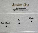
Jundac One
|
Last revision on October 2009
|
|
 Click here to enlarge the picture
|
- Non oversampling DAC
- 20 bit DAC resolution (PCM1702)
- Open loop I/V converter
- Low filtered output
- Optional external clock for very low jitter
- Six regulators
- Bipolar low noise solid states (MPSA18)
- Four digital input
- High toroidal power transformer (300VA)
- Three power transformer
- Inductor filtering
- Small capacitors power supply (300µF)
|
|
About design
|
A non-oversampling DAC might not be seen as low cost or poor quality DAC.
Implementing top-end NOS DAC with real DAC chip, open loop I/V converter and strong power supply
cut with preconceived ideas of digital World. Some of digital default come from digital
filter; forget metallic and foggy sound and comes to realistic, detailed and natural music.
The Jundac One is a top-end 20 bit NOS DAC; it is my personal implementation of Digital Decoder Pro.
When designing high quality device, each stage is important:
- digital (with or without digital filter),
- DAC chip,
- i/v stage,
- low pass filtering,
- regulators,
- power supply (transformers),
- passive components and wiring,
- grounding and link to earth,
- drawing PCB,
- chassis and mechanical vibrations.
You must care about each detail, everything is important. Digital filter is important in global
quality, but each stage is as important.
Relative audio quality level
To obtain best sounding, ensure to power on 48 hours before listening.
|
|
Schematic
|
Go to to Digital Decoder pro's page
|
The bit alignment is provided by the Digital Decoder. The data stream
feed a Burr-Brown PCM1702 20 bit DAC chip followed by feedback free I/V stage with very sweet low pass
filter. Analog stage is similar to analog stage used in my preamplifier model 4 and model 3.
The low pass filter is first order filter cutting at 25KHz. The 160nH inductor is...for fun and cut
at very high frequency.
Pictures of analog signal:
|
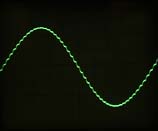
Low filtered output signal
|
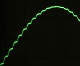
Detail
|
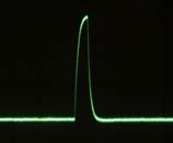
Dirac impulse response
|
|
|