|
|
|
|
Preamplifiers
|
|
Preamplifier Model 3
|
Last revision on July 2007
|
|
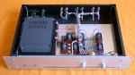 Click here to enlarge the picture
|
- Zero feedback line stage preamplifier
- Bipolar Solid states (MPSA18)
- Enhanced regulated power supply (LM317)
- Three lines input
- Mechanical switches
- High toroidal power transformer (300VA)
- Small capacitors power supply (300µF)
- Low cost realization
|
|
Listening results
|
This preamplifier is my second preamplifier (1995-1998). Design reduce components and price compared with
model 2, bipolar transistors replaces input FET, filtering capacitors dramatically reduce.
First listening, surprise by missing glittering and brilliancy in high frequencies. Tweeters seem to
switch off. Tonal balance is not conventional, voices are nice, bass are fast and depth, with great
dynamic. Global listening is easy and simple. Power amplifier work without impressive effects,
everything seems so natural.
Finest and beauty could describe this device.
To obtain best sounding, ensure to power on 48 hours before listening.
Relative audio quality level

|
|
Linear stage
|
Schematic diagram and part list are revision-B of this device (1998).
Linear stage use MPSA 18 common base bipolar transistor. Compared to MPSA42, MPSA18 sound better. The stage stills an open loop (feedback-free). The total gain is 2.727 (8.7db), permit to use volume potentiometer to a large scale.
Input inductor (0.8mH) reduces HF frequencies that come from CD. Result depend on source, you never obtain negative effect on sound quality, but can obtain more softness.
All 10µF are MPK 400V (Polypropylene) from SCR. (very nice sonority). Some current were adjusted by comparative listening test: output transistor (13.45mA) and driving current of common base transistor (12.85mA).
|
|
Power supply
|
It starts (of course) with big 300Va transformer. (See article about power supply).
First schematic use 3 000µF chemical capacitors. Reducing capacity to 300µF, increase sound quality. Bass are more depth, fast, full, metallic aspect decrease. Space sonority is less confused. But hum and noise increase!
I use resistor between input and output the LM317 regulator (220 ohm). Unfortunately it introduce rumble, but greatly increase sound quality.
I keep the 543 ohm resistors to shunt the rectifier diodes. Because of excessive power dissipation, I switch on theses resistors only when I (really) listen to music. This tip reduce subjective level in medium-treble.
10µF are MPK from SCR.
About music, listening condition, system... go to questions page.
|
|
|