|
|
|
|
Preamplifiers
|
|
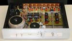
Preamplifier Model 4
|
Last revision on July 2009
|
|
 Click here to enlarge the picture
|
- Open loop line stage preamplifier
- Three open loop regulator
- Bipolar low noise solid states (MPSA18)
- Six lines input
- Relay switches
- High toroidal power transformer (300VA)
- Inductor filtering
- Small capacitors power supply (300µF)
- Fine rectifier diodes
|
|
Listening results
|
This preamplifier is my last realization (2007/2008).
It is very expressive with non oversampling DAC.
This couple gives awesome dynamic and definition. Voices are very natural, sweet,
and detailed, bass are fast and depth. Listening seems so easy and natural.
Model 4 is real Top-end preamplifier. To reach this quality level, a particular attention was paid on following points:
Relative audio quality level

To obtain best sounding, ensure to power on 48 hours before listening.
|
|
Line stage
|
Line stage is same as model 3 preamplifier,
it uses MPSA18 common base bipolar transistor. The stage stills an open loop (feedback-free).
The total gain is 2.727 (8.7db), permit to use volume potentiometer to a large scale.
Input inductor reduces HF frequencies that come from CD. Result depend on source,
you never obtain negative effect on sound quality, but can obtain more softness.
All 10µF are MPK 400V (Polypropylene) from SCR. (very nice sonority).
|
|
Power supply
|
Power supply is totally different from model 3. A particular attention and many hours
listening test, were done to select active and passive components. The rectifiers (BYW98-200)
feed a big inductor. This (8H) inductor is the primary of toroidal transformer.
Three 100µF (Elna Silmic II) + 4 x 10µF MKP (SRC) are used to slice tension. Three open loop regulators give constant voltage.
First regulator supply output line stage and second regulator for each channel.
All the stages are open loop (feedback-free).
About music, listening condition, system... go to questions page.
|
|
Benefit of big inductor
|
After the big inductor, output tension in sinusoidal.
|
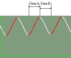 FIGURE 1 - output inductor tension.
|
Time A - Charging capacitor, supply current come from the inductor.
Time B - Discarding capacitor, supply current come from the capacitor.
...
during half time, capacitors are charging, during half time capacitors are discharging. This completely
different from CLC solution. It matches with "Shared Current Power Supply" concept.
For a complete discussion see Power supply in small current device pages.
|
|
Silent power supply, a simple PCB wiring
|
|
PCB drawing is according to "Silent power supply".
|
 FIGURE 2 - silent power supply.
|
In standard power supply, current for charging capacitors and current for audio stage are mixed on
length PCB wire. Mixing this high, low frequency (50/60Hz), current is not good for sound. (Remember during half time, capacitors are
charging, during half time capacitors are discharging.)
In "Silent power supply", current path are separated. Standard wiring gives foggy and metallic
sound. While "Silent power supply" gives very soft and detailed sound with very depth bass.
This drawing matches with "Shared Current Power Supply" concept.
For a complete discussion see Power supply in small current device pages.
|
|
Passive components and wiring
|
Electrolytic capacitors are Elna Silmic II, 10µF and 1µF are MKP from SCR, smaller values are KP from Wima.
Each capacitor contributes to softness and realism.
For a complete discussion see Comparing electrolytic capacitors.
|
|
|