|
|
|
|
Non-oversampling Digital Audio Converter
|
|
Digital decoder - January 2009
|
Last revision on October 2009
|
|
Non-oversampling DAC are common DAC since few years.
Related link:
Non-oversampling Digital filter-less DAC Concept by Ryohei Kusunoki
Most of NOS DAC was made with PHILIPS TDA1543 chip. It is very interesting to build NOS DAC
with other chips. Standard DIR (digital interface receiver) provide easy wiring to connect Philips
TDA1543 or TDA1541 chip. It is the reason why these chips are very popular.
TDA154X are 16bit chips and out of production today. Many diyaudio-people want to build their own
DAC with other chip like Burr-Brown PCM1704 (24bit) or PCM56 (16bit). These chips need more glue logic.
It can be a big problem, and some people forget their project. For this, I build the digital decoder.
The digital decoder is a first board providing easily way to build your own 16 to 24 bit, 32K to 192KHz NOS DAC.
You can concentrate your work only on analog part. Digital decoder can run with or without an external audio clock to reduce jitter in DAC process.
|
|
Technical documentation
|
|
Details

|
|
Technical description
|
|
|
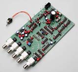
Digital decoder use Cirrus CS8416, 32K to 192KHz DIR
(digital interface receiver) chip. CS8416 provide digital de-emphasis needed for reading some CD
recorded with pre-emphasis and four inputs. Each input can be RCA, BNC or XLR with 75 or 110 Ohm.
CS8416 can run in master or slave mode if an external clock is active.
A jumper allows matching with DAC resolution: 16bit, 18bit, 20bit, 24bit.
A serial shift register provide 16 to 24 bit right aligned data. Data for LEFT and RIGHT channel are aligned,
you dont need more logic. Before output, digital data are re-clocked to avoid digital delay and reduce
jitter and noise.
For convenience, Bit clock and Word clock are available with normal and complementary value.
|
|
Sample connect
|
|
|
Connecting DAC chip to digital decoder is very easy. No glue logic is needed, it reduce digital noise
and jitter.
DAC chip that you can use (other reference, email me)
Texas instruments/Burr-brown
- PCM56
- PCM1702
- PCM1704
Obsolete
- PCM58
- PCM61
- PCM63
- PCM1700
|
Analog Devices
- AD766
- AD1851
- AD1866
Obsolete
- AD1856
- AD1860
- AD1861
- AD1862
- AD1864
- AD1865
- AD1868
|
|
|
External clock
|
To put system on top, you can use an external master clock for CD player and DAC.
This clock is not necessary. Using it greatly reduce jitter and improve audio rendering.
In this configuration, you use a single crystal for CD and DAC clock.
Here is a simplified schematic using 11.2896MHz crystal oscillator.
Replace your internal crystal oscillator by external oscillator.
Most of CD player use 11.2896MHz or 16.9344MHz. With 16.9344MHz use divide by 3 clock divider.
Some new CD has external input clock plug. In this case you dont need to replace internal clock.
|
|
Schematic diagram
|
|
|
|
|