|
|
|
|
Digital to analog converter
|
|
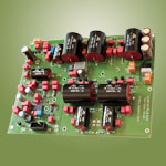
Jundac Five
|
Last revision on July 2011
|
|
 Click here for more pictures
|
- Non oversampling DAC
- 16 bit DAC resolution (TDA1545A)
- Open loop I/V converter
- Semi parallel regulator
- Low filtered output
- Optional external clock for very low jitter
- Constant 75 ohm load for digital section (PCB + loaded lines)
- Low noise regulators (6x)
- Bipolar low noise solid states (BC550C/560C)
- One digital input
- High toroidal power transformer
- Two power transformer
- Small capacitors power supply (300µF)
|
|
About design
|
The Jundac Five is a 16bit non-oversampling digital to analog converter.
It integrates one S/PDIF or AES/EBU input, an optional input clock and stereo fixed analog output.
The DAC chip is Philips TDA1545A; it can operate from 32kHz to 192kHz sampling frequency.
The I/V stage uses discrete, solid state technology, in an open loop (feedback-free) configuration.
A comfortable environment coupled to a particular way to drive IREF pin allows reaching an incredible
quality audio level.
A non oversampling DAC don't use any digital filter. Data coming from CD are directly converted to analog;
there is no coloratura introduced by digital filtering, noise shaping or dithering.
Before output, the signal is smoothed by a sweet first order low pass filter. To reach best listening quality,
it can be coupled to an synchronous or asynchronous low jitter clock.
Power supplies in a DAC are critical to the overall design. The Jundac Five uses six very low noise
separate regulators. These power supplies use polypropylene capacitors and two separated power transformers.
To achieve the full music sonic attributes, we recommend using 200VA to 300VA power transformer
for analog section. This transformer powers the DAC stage and the analog section (I/V converter
and low pass filtering).
When designing high quality device, each stage is important:
- digital (with or without digital filter),
- DAC chip,
- i/v stage,
- low pass filtering,
- regulators,
- power supply (transformers),
- passive components and wiring,
- grounding and link to earth,
- drawing PCB,
- chassis and mechanical vibrations.
You must care about each detail, everything is important. Digital filter is important in global
quality, but each stage is as important.
Relative audio quality level

To obtain best sounding, ensure to power on 48 hours before listening.
|
|
Technical documentation
|
|
|
Technical description
|
|
|
The Jundac Five use Cirrus CS8416, 32K to 192KHz DIR
(digital interface receiver) chip. The CS8416 provides digital de-emphasis needed for reading some CD
recorded with pre-emphasis. The input can be RCA, BNC or XLR with 75 or 110 Ohm.
Jundac Five auto switches to external clock when signal is detected.
Before DAC, digital data are re-clocked to avoid digital delay and reduce jitter and noise.
The DAC chips TDA1545A from Philips allows 16bit resolution. PCB is 75 ohm compliant, all lines are loaded
with 75 ohm terminal resistors.
|
|
Schematic
|
|
|
The data stream feed a Philips TDA1545A 16 bit DAC chip followed by feedback
free I/V stage with very sweet low pass filter. The low pass filter is first order filter cutting
at 70KHz using polypropylene film and foil capacitor. The BC550C/560C were chosen for their high quality sounding,
each transistor are matched.
The Jundac Five uses very low noise regulators:
- LT1763 for the digital section,
- LT3080 for analog and DAC stage.
The analog section use three very low noise regulator LT3080 form Linear Technology in a semi-parallel configuration.
|
|
|
In a semi-parallel regulator, i3 is adjusted to never become negative. Thus, the analog stage is never
directly powered by the regulator, this improve transient response. The LT3080 ensure line regulation.
Pictures of analog signal:
|
Low filtered output signal
|
Detail
|
Dirac impulse response
|
|
|
IREF current
|
The IREF pin is the secret of the TDA1545A
I never find that datasheet for TDA1545A is very clear.
There are a lot of interrogations about the interesting IREF pin. In our prototype
we test various configurations, starting with the standard one recommended by Philips.
After some measurement, it appears that some information is omitted like the full
scale current output is proportional to VDD. The most important find is that
sound quality depends of IREF pin driving method.
|
 Diagram of VERF
|
The incredible audio quality level reach by this kit is due to original way
to manage reference current pin. This way is different from Philips recommendations.
We develop a reference tension in discrete technology dedicated to this chip.
The TDA1545A reaches unknown dimensions with very large and strong bass,
good definition and fine treble. It changes from all other realizations.
Low noise transistors and high quality capacitors (no electrolytic capacitors)
are used to drive this crucial pin.
|
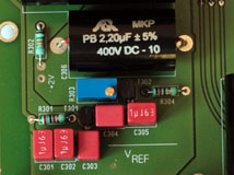
VREF stage
|
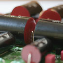
Detail of 10µF 100V stacked capacitor for IREF filtering
|
Cliping when VREF exceed max capabilities
|
|
|
Power supplies
|
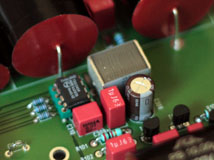
Power supplies in a DAC are critical to the overall design. The Jundac Five uses six very low
noise regulators: three for the analog section and three for digital section. These power supplies
use polypropylene capacitors and two separate power transformers. For electrolytic capacitors,
Elna Silmic II for analog, and Nichicon LF for digital, are used. Ultra fast recovery
surface mount rectifier diodes are used in analog and digital stages.
|
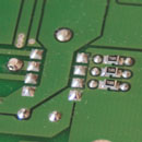
Detail of 75 ohm load resistors on TDA1545
|
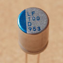
Nichicon LF for digital ps
|
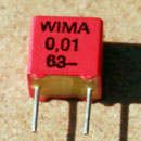
Wima polypropylene film cap
|
|
 Diagram of power supply
|
There is three LT1763 for digital section in a cascaded configuration (+8V, +5V, +3.3V) and
three LT3080 for analog section in a cascaded configuration (+27V, +22V, +5.6V).
|
|
Decoupling
|
We took particular attention in decoupling. Digital data, and particularly the clock signal,
carry digital information with high (X MHz) and low frequency (20Hz to 20kHz) noise modulation.
This modulation has direct impact on audio rendering. It is important to provide wide band decoupling.
Jundac Five uses high frequency capacitors mixed with high quality MKP capacitors.
It results in a very natural and analog sound without metallic aspect.
|
Detail of decoupling
|
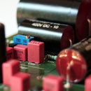
Detail of decoupling
|
Detail of decoupling
|
|
|
|